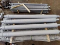
Luffing Cylinder
The company was established in 1985. Since its establishment, it has been committed to R&D and production of a complete set of hydraulic cylinders for truck cranes, hydraulic cylinders for special vehicles, a complete set of pump truck (boom and pumping) cylinder series, truck-mounted crane cylinders, sanitation truck cylinders, aerial work vehicles, oil cylinders, forklift oil cylinders, large special high-pressure oil cylinders and other products.
The company took the lead in passing the ISO9001:2008 quality management system certification in the industry. Now it covers an area of more than 50 acres and has fixed assets of 100 million yuan. At present, the product technology is at the leading level in China, and the products meet the needs of our customers. Recognition and praise of medium-sized enterprises. Products all over the country more than 30 provinces, municipalities and autonomous regions.
Production Capacity
The hydraulic cylinder production workshop has more than 200 sets of various equipment, which can produce and process various hydraulic cylinders with a maximum inner diameter of 1.45 meters and a maximum stroke of 15 meters, ranging from low pressure 16MPa to high pressure 70MPa, with a production capacity of 50,000 sets.
Our Certificate
ISO9001 Quality System, High-tech Enterprise, Specialized New Enterprise in Shandong Province More than 10 patents.
Partners
Main supporting enterprises include Liugong Group, Hunan Pengxiang Xingtong Automobile Co., Ltd., Jining Sitong Engineering Machinery Co., Ltd., Qingdao Jiuhe Heavy Industry Machinery Co., Ltd., Henan Feilong Engineering Machinery Manufacturing Co., Ltd., Mudanjiang Special Purpose Vehicle Manufacturing Co., Ltd., Hangzhou Forklift Co., Ltd. and dozens of other well-known domestic enterprises. There are more than 100 product varieties, covering most types of engineering machinery. In the future, as the company's R&D capabilities improve, more products will cover more fields.


Benefits of Luffing Cylinder
Increased Efficiency
Luffing cylinders enhance the efficiency of hydraulic systems by allowing for rapid and precise movements. This speed not only saves time but also increases productivity, enabling operators to complete tasks more quickly.
Improved Safety
The precise control offered by luffing cylinders contributes to safer operations. By lowering the risk of tipping and ensuring stable load handling, these cylinders help prevent accidents and injuries in the workplace.
Versatility in Applications
Luffing cylinders are versatile and can be utilized in various applications, from construction and shipping to manufacturing and automotive industries. This adaptability makes them an essential component in modern hydraulic systems.
Reduced Downtime
The enhanced reliability offered by luffing cylinders translates to reduced downtime. With fewer mechanical failures and maintenance requirements, operators can focus on productivity instead of dealing with equipment breakdowns.
| Name | Model | Stroke | Installation distance | Related pressure | L1 | L2 | L3 |
| Luffing hydraulic cylinder for crane | 20T Luffing hydraulic cylinder 2 | 840 | 1277 | 31.5 | 1277 | 190 | 90 |
| 4060 Luffing hydraulic cylinder 2 | 968 | 1320 | 30 | 1320 | 181 | 88 | |
| 6.3 TLuffing hydraulic cylinder 2 | 965 | 1315 | 31.5 | 1315 | 170 | 70 | |
| 200 Luffing hydraulic cylinder 2 | 891 | 1305 | 31.5 | 1305 | 216 | 106 | |
| 360 Luffing hydraulic cylinder 2 | 1003 | 1446 | 31.5 | 1446 | 234 | 119 | |
| 400 Luffing hydraulic cylinder 2 | 996 | 1440 | 31.5 | 1440 | 219 | 104 | |
| 500 Luffing hydraulic cylinder 2 | 1063 | 1513 | 31.5 | 1513 | 223 | 113 | |
| 600 Luffing hydraulic cylinder 2 | 1120 | 1571 | 31.5 | 1571 | 224 | 114 | |
| 2200 Luffing hydraulic cylinder 2 | 1260 | 72 | 31.5 | 1260 | 272.5 | 152.5 | |
| 2800 Luffing hydraulic cylinder 2 | 725 | 1440 | 32 | 1400 | 163 |
Application of Hydraulic Luffing Cylinder
The installation process for an adjustment hydraulic cylinder may vary depending on the application and equipment involved. However, here are some general steps to consider when installing an adjustment hydraulic cylinder:
Prepare the Work Area: Ensure that the work area is clean, clear of debris, and provides enough space to maneuver the hydraulic cylinder and associated components. This will help facilitate a smooth installation process.
Select the Proper Cylinder: Choose a hydraulic cylinder suitable for the specific application, considering load capacity, stroke length, and mounting requirements. Refer to the manufacturer’ s specifications and recommendations for the appropriate cylinder selection.
Mounting Bracket or Clevis: If required, mount the cylinder to a bracket or clevis on the equipment or system where it will be installed. Ensure the mounting bracket or clevis is securely attached and aligned with the cylinder.
Connect Hydraulic Lines: Connect the hydraulic lines to the cylinder. The hydraulic lines should be appropriately sized, have the correct fittings, and be compatible with the hydraulic system. Use appropriate seals or fittings to prevent hydraulic fluid leakage.
Secure the Cylinder: Ensure the adjustment hydraulic cylinder is securely fastened to the equipment or system. This may involve tightening mounting bolts or other fasteners according to the manufacturer’ s recommendations. Verify the cylinder is aligned correctly and free from any interference hindering its movement.
Hydraulic Connections: Connect the hydraulic lines from the cylinder to the hydraulic power source. This typically involves attaching the lines to control valves, pumps, or other hydraulic components. Pay attention to proper routing, secure connections, and avoiding kinks or sharp bends in the lines.
Test and Adjust: Once the adjustment hydraulic cylinder is installed, thoroughly check to ensure proper functionality. Test the cylinder’ s extension and retraction by operating the hydraulic control system. Verify that the cylinder moves smoothly without binding or excessive resistance. Adjust the hydraulic pressure, flow, or control settings to achieve the desired positioning or adjustment.
Safety Precautions: Always keep safety as the top priority during installation. Follow proper safety procedures, such as wearing a protective mask and following lockout/tagout procedures when necessary. Be aware of potential hazards, such as high pressure in the hydraulic lines, sharp edges, or heavy loads associated with the equipment.
Specification And Maintenance Of Luffing Cylinders


Specifications
Capacities: Luffing cylinders come in different capacities. A common capacity range is from 800kg to 5000kg. The capacity of a luffing cylinder is usually given in terms of maximum weight.
Stroke length: This is the distance between the fully retracted and fully extended positions of the luffing cylinder. It is usually expressed in millimeters (mm) or inches. A typical stroke length for a luffing cylinder is 700mm.
Diameter: This is the width of the luffing cylinder. It determines the force it can carry. The diameter of a luffing cylinder is usually expressed in millimeters (mm) or inches. A standard diameter is 100mm.
Operating pressure: Luffing cylinders have a maximum operating pressure under which they can function. This is usually expressed in pounds per square inch (psi) or bars. A typical operating pressure for a luffing cylinder is 160 bars.
Maintenance tips
Regular inspection: Regularly check the luffing cylinder for any sign of damage or leak. This helps to avoid more severe problems.
Cleaning: Always keep the luffing cylinder clean and free from debris. Cleaning can prevent the ingress of contaminants that can increase wear and tear.
Lubrication: Proper lubrication is important for the performance and longevity of the luffing cylinder. Regularly apply lubricants to the moving parts to reduce friction and wear.
Seal inspection: The seals of the luffing cylinder are crucial for preventing leakage and contamination. Regularly inspect the seals for damage and replace them if necessary.
Pressure check: Regularly check the operating pressure to ensure it is within the recommended range. This is important for safety and optimal performance.
Operating tips: Avoid overloading the luffing cylinder beyond its rated capacity. Also, avoid sudden impacts or movements that can damage the cylinder.
|
Designed For |
Single Acting Ram Cylinder- Landfill truck tipper |
|
Stage |
3~4stage cylinder |
|
Each stage OD |
290/260/230mm and 248/221/196mm |
|
Working Pressure |
Working 7-15MPA , MAX working 21MPA ,Testing :25MPA |
|
Tipping Weight |
15--150Ton |
|
Seal Type |
Parker,NOK, BUSAK SHAMBAN or as customer's requirement |
|
Stroke |
6000—12000mm |
|
Tube |
27simn |
|
Warranty |
We offer 12 months warranty |
Certifications


FAQ
We're well-known as one of the leading luffing cylinder manufacturers and suppliers in China. If you're going to buy high quality luffing cylinder, welcome to get more information from our factory. Also, customized service is available.
Boom Luffing Cylinder, Luffing Cylinder, Crane Luffing Cylinder